
An engineering drawing is one of the most important documents to hand off when you outsource an electronic assembly. An engineering drawing acts as the translator between the design and the physical unit that comes off the line. When the drawing is put together well, your electronic assembly partner can build, inspect, and test your product exactly the way you intended. When it’s missing information, you open the door to delays, RMAs, and units that technically match the BOM but miss the design intent entirely.
Here’s everything a strong engineering drawing package should cover, and why each piece matters to the people building your assemblies.
- Title Block and Revision Control
Every drawing should begin with the basics: part number, revision letter, drawing title, sheet size, drawn-by and approved-by fields, and the date of release. Nailing the basics of your drawing is important because they can carry real weight on the shop floor.
A clear revision history tells your electronic assembly partner exactly what changed between Rev B and Rev C, so operators and quality inspectors are always building to the current standard. Without tight revision control, an electronic assembly partner could unknowingly build to an outdated drawing, leading to a batch of units that require rework or are shipped incorrectly.
Tip: have multiple team members double-check the basics of your drawing before anything else. Sometimes, these details can get overlooked once your team is deeper in the design process.
- Dimensions and Tolerances
After you’ve got the basics, the next portion of a drawing to flesh out are dimensions and tolerances. Overall dimensions, critical feature dimensions, and their tolerances tell your electronic assembly partner what “correct” looks like. This includes:
- Board outline and mounting hole locations for PCB assembly
- Component height restrictions (especially in enclosure-constrained designs)
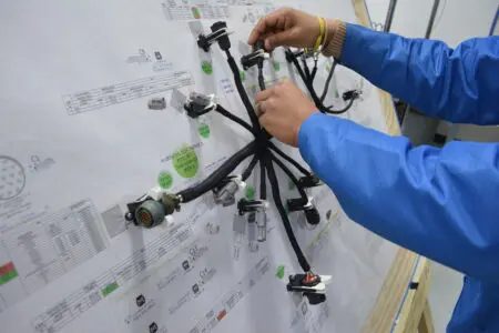
- Keep-out zones for connectors, heat sinks, or mechanical hardware for cable & wire harness assembly
- Tolerance stack-up for mating parts, such as panel-mount connectors or press-fit hardware
Tolerances matter most where your assembly interfaces with other electronics such as another cable or wire harness assembly, a PCB assembly, or in a larger panel/enclosure. A dimension without a tolerance leaves interpretation up to the operator, and that’s a gap you want closed on paper, never on the line.
Tip: working with a partner that prioritizes design for manufacturability will help you assess the dimensions and tolerances in your drawing. They will help you ensure your drawing is fit for manufacturing your assemblies at scale.
- Materials, Finishes, and Special Processes
If your assembly calls for a specific PCB laminate, a particular surface finish (ENIG, HASL, immersion silver), or a conformal coating, this belongs explicitly on the drawing. The same goes for any secondary processes: staking, potting, underfill, or adhesive application around large components subject to vibration.
This section is where a lot of design intent lives that never shows up in a BOM line item. A resistor is a resistor on paper, but if it needs to be conformal coated because the final product operates in a humid or corrosive environment, that requirement has to be called out clearly, or it gets missed.
Tip: share as much as you can about the final application of your assembly with your EMS partner. This helps them understand the exact care needed when building the electronic assembly.
- Reference Designators Tied to the BOM
Now, it is time to tie your drawing back to the other most important document your electronic assembly partner needs, the bill of materials, or BOM.
Every reference designator on the drawing should map cleanly to a line item on the bill of materials. This sounds obvious, but mismatches between the silkscreen, the drawing, and the BOM are one of the most common causes of build delays. When designators line up perfectly across all three documents, your EMS partner’s procurement and manufacturing teams move faster with fewer clarifying questions back to you.
Tip: to learn more about what is required in a BOM for electronic assembly, check out our latest guide here.
- Assembly Notes and Special Instructions
Next, it is time to share any additional details with your electronic assembly partner. This is often the most valuable and most overlooked section of a drawing.
Assembly notes capture anything your electronic assembly partner’s manufacturing team needs to know outside a dimension or a BOM line. Some examples of note topics include:
- Torque specifications for mechanical fasteners
- Wire harness routing or dress requirements
- Cleaning requirements post-reflow, especially for high-reliability applications
- Test points and functional test requirements
- Labeling, marking, or serialization instructions
Tip: think of this section as a direct line of communication to the assembly operator. A well-written note here can help prevent rework.
- Inspection Criteria and Acceptance Standards
Lastly, set your inspection expectations with your electronic assembly partner. Calling out the applicable IPC class (commonly Class 2 for general industrial electronics or Class 3 for high-reliability applications like aerospace, defense, or medical devices) sets the acceptance standard your electronic assembly partner will inspect against.
Without this, quality teams default to a general standard that may run looser or tighter than what your application actually requires.
Tip: a control panel destined for a food and beverage processing line has different environmental and cleanliness expectations than a board going into a data center server rack. Spelling out the standard up front keeps everyone aligned on what “pass” means.
Where a Strong Electronic Assembly Partner Adds Value: Design for Manufacturability
Across industries, such as automotive, food and beverage, aerospace and defense, data centers, the electronic assemblies with the fewest production issues almost always trace back to the most complete drawing packages.
However, even a well-documented drawing can include design choices that are difficult to manufacture repeatably at scale. This is where a good electronic assembly partner earns its keep. An electronic assembly partner that offers Design for Manufacturability (DFM) services will review your drawing package and BOM before production starts, flagging things like tight component spacing that complicates automated placement, footprints prone to tombstoning, or connector placements that make rework difficult down the line.
DFM feedback is about adapting your design so it can be built consistently, run after run, with high first-pass yield and fewer surprises. The best partnerships treat the engineering drawing as a living conversation between your team and your assembly partner’s process engineers, revisited throughout the life of the program instead of handed off once and left alone.
The Bottom Line
A complete engineering drawing gives your contract manufacturer everything needed to build your product right the first time: dimensions and tolerances, materials and finishes, polarity and orientation, assembly notes, and clear inspection criteria, all tied together with tight revision control. Pair that with a manufacturing partner who reviews your designs proactively through DFM, and you’ve built a foundation for repeatable, high-quality production runs.
To learn more about how PGF Tech can help you with electronic assembly including DFM support, contact us here: https://www.pgftech.com/contact-us/